Intro (Building AND gates the wrong way)
The circuit built in this video has as a goal mainly introducing the problem I want to discuss. Check the video first:
It is a very simple build, and a good “first project to build on a breadboard”. If you’ve ever built anything more elaborate, probably you can skip this, and move on to Part 2: Diodes&Diodes.
Most of this document will be targeted at people very new to breadboarding.
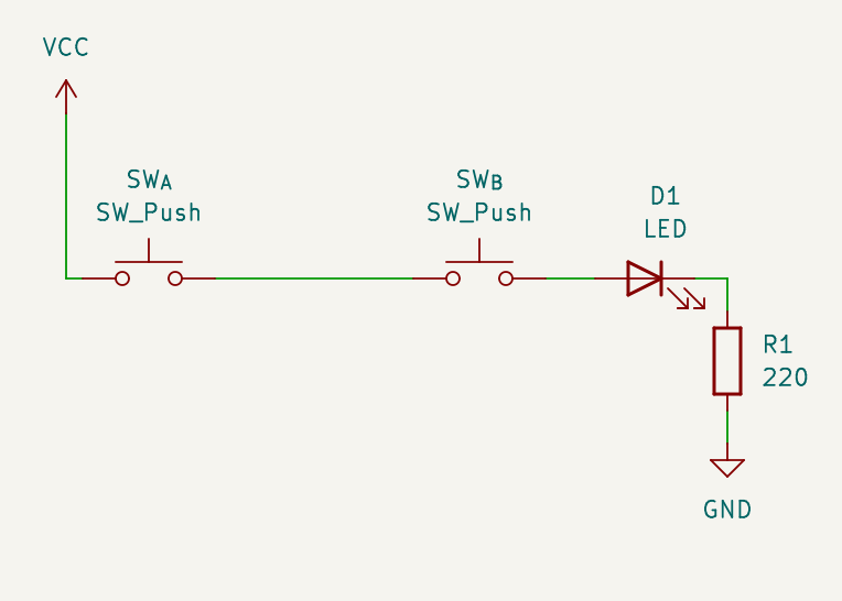
Schematics

What do you need
- 2 × push buttons. They should have pin spacing compatible with a breadboard. Some popular and widely available models have 5.08mm pin spacing in one dimension, and 7.62mm in the other, those fit perfectly over the central groove in a breadboard.
- 1 × LED. Any color will work
- 1 × resistor. The value for the resistor should be at least 200Ω to avoid burning the LED; 220Ω is a typical value that will give you a very bright output. If you prefer a dimmer LED, you can try higher values and decide what you like (the higher the resistor value, the dimmer the LED will be).
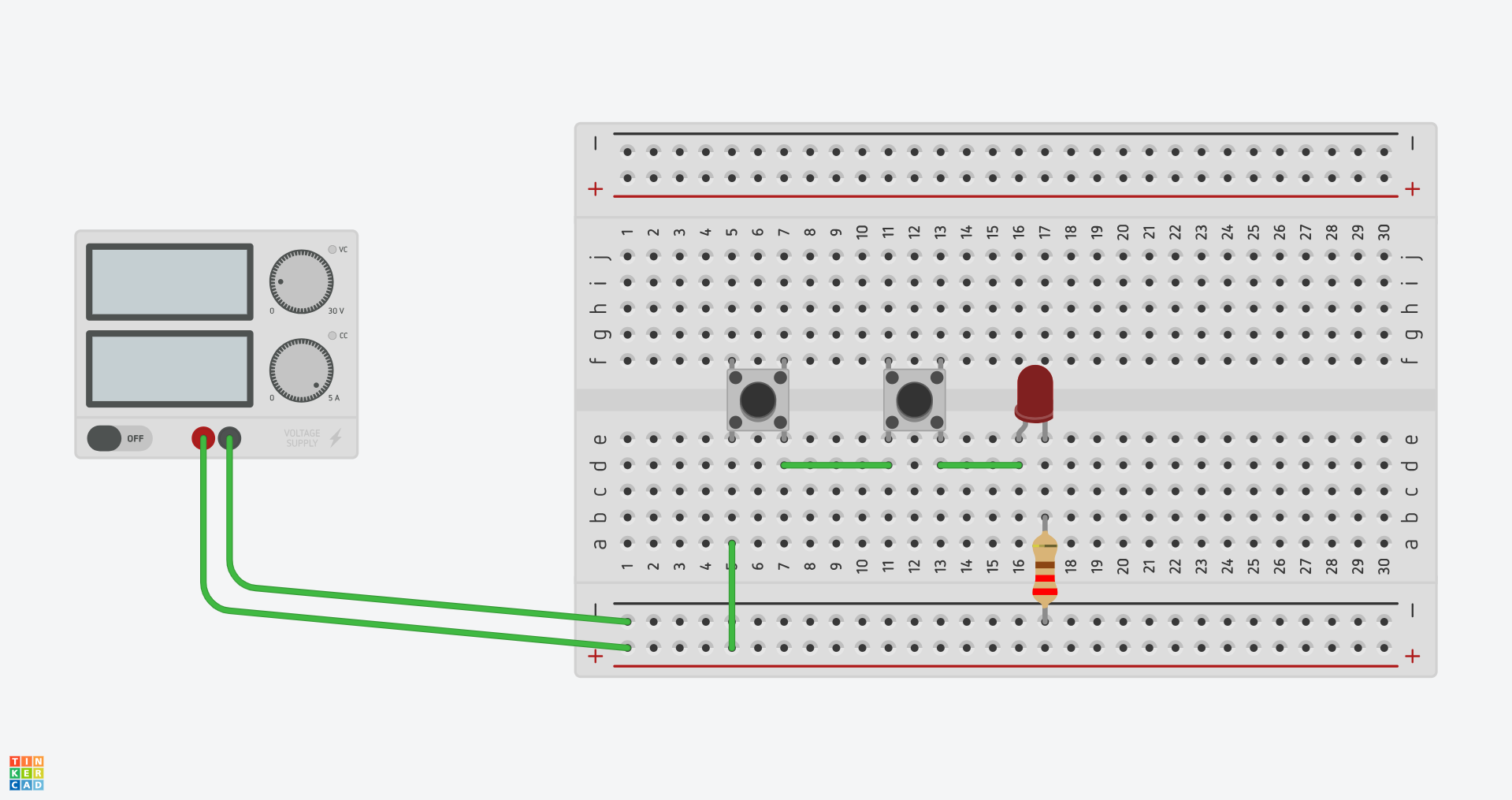
Breadboard Layout
