An 8-bit numeric display
This is a description of a display for showing values of an 8-bit signal. This is useful for building and debugging breadboard digital circuits working with digital numbers.
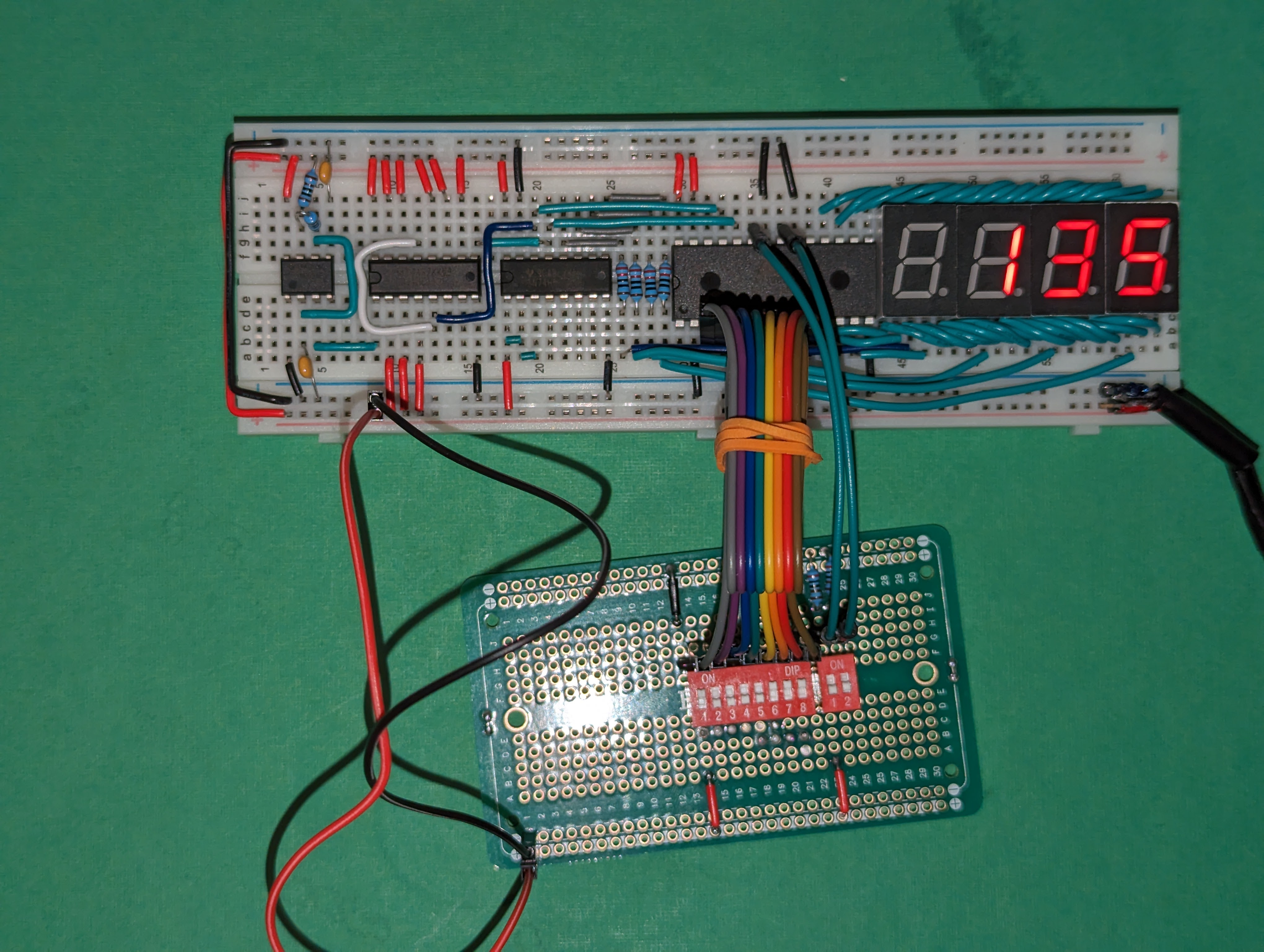
It’s main features are:
- Can be switched (by a control signal) to display data in both decimal and hex.
- Can interpret data as unsigned numbers (0 to 255), or signed two’s complement values (-128 to 127). This can also be switched through a control signal.
- has its internal clock, all the input it needs is the input data, power, and mode selection lines.
It’s inspired in Ben Eater’s output register, but this is just the display (it does not contain register functionality). I decided to keep it as a separate unit that I can attach to any register to debug.
Building the display

Materials
- R1: 1KΩ
- R2: 100KΩ
- R3-R6: 220Ω (you can choose a slightly different value, this controls the brightness)
- C1, C2: 0.01µF (equivalent to 10nF) ceramic. Usually labeled “103”
- U1: LM555 timer IC
- U2: 74HC112 dual J-K flip-flops. This is different than Eater’s design that used a 74LS76 (obsolete). Other J-K flip-flop ICs will work OK but may have different pin out.
- U3: 74HC139 dual 2:4 decoder
- U4: AT28C64B EEPROM. You’ll have to pre-program it (see below)
- U5-U8: 7-segment display, common cathode. For breadboard use look for some with the pins at the top+bottom of the digit, and pins at the right spacing.
All ICs should be in DIP package if you’re building in breadboards.
You can also choose TTL compatible components (LS or HCT families for the 74 series, and NE555 for the timer IC). As long as you’re consistent, it’s the same; all external inputs come into the EEPROM, which accepts both TTL and CMOS inputs.
Data sheets
Preparing the ROM
The ROM image is generated by a Python script. I tried to make it easy to change. I’m also providing a pre-built ROM file if you want to use mine unchanged.
You will need an EEPROM programmer to write the ROM. The image generated only uses the lower 4KB (leaving the other 4KB unused). It would be possible to add other modes there if desired.
The Config section has a few settings that you can fiddle with; FONT is something you
can change without changing the circuit if you want to provide different selection of
segments or representable values. ROM_LAYOUT is used to customize the mapping of
segment to ROM pins; this has been configured for my breadboard layout so that the wires
from ROM to the segment stay in the same side of the breadboard and are tidier.
The generate_text() should produce the text representation for an 8-bit value in the
selected mode. shuffle() takes care of adjusting the bits described in the font to the
output pin layout selected.
If you set an invalid mode, the display should show ---- (four dashes).
Possible improvements
- Having one resistor per digit makes the current fixed per digit, which results in symbols with many segments (like the digit 8) dimmer than symbols with less segments (like the digit 1). It would be better to have resistors in each one of the output lines from the ROM, but using a breadboard ends up being a bit tight to do this
- I’m exploring a version where I replace the 112+139 for a single PLA (ATF16V8); that would provide a bit of extra physical space for other improvements.